 Undoubtedly the Baofeng UV-5Rx delivers a lot of radio for your buck. However some models in the range have a bad reputation for the transmitted audio sounding soft and muffled.
In 2013, Remco PA3FYM obtained the schematics of the radio and devised a modification where transistor Q17 of the VOX is re-purposed as preamplifier in the microphone audio circuit. It works wonders for your radio. For people needing a bit more visual guidance, below is a walktrough of how I did this to my Baofeng UV-5RA.
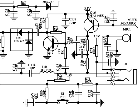
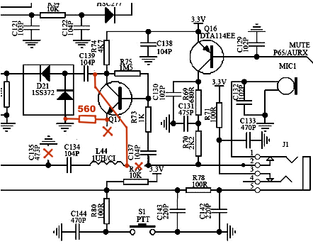
On the left you find the original schematics of the microphone and vox circuits. On the right, I’ve marked the modifications we’re about to do in red.
 |
 |
Step 1: Open the radio
Open up the Baofeng UV-5RA. There is plenty information online on how to do this, check out the teardown at takapart for instance. You need to open the radio up to the point that you can access the components on the back of the keypad.
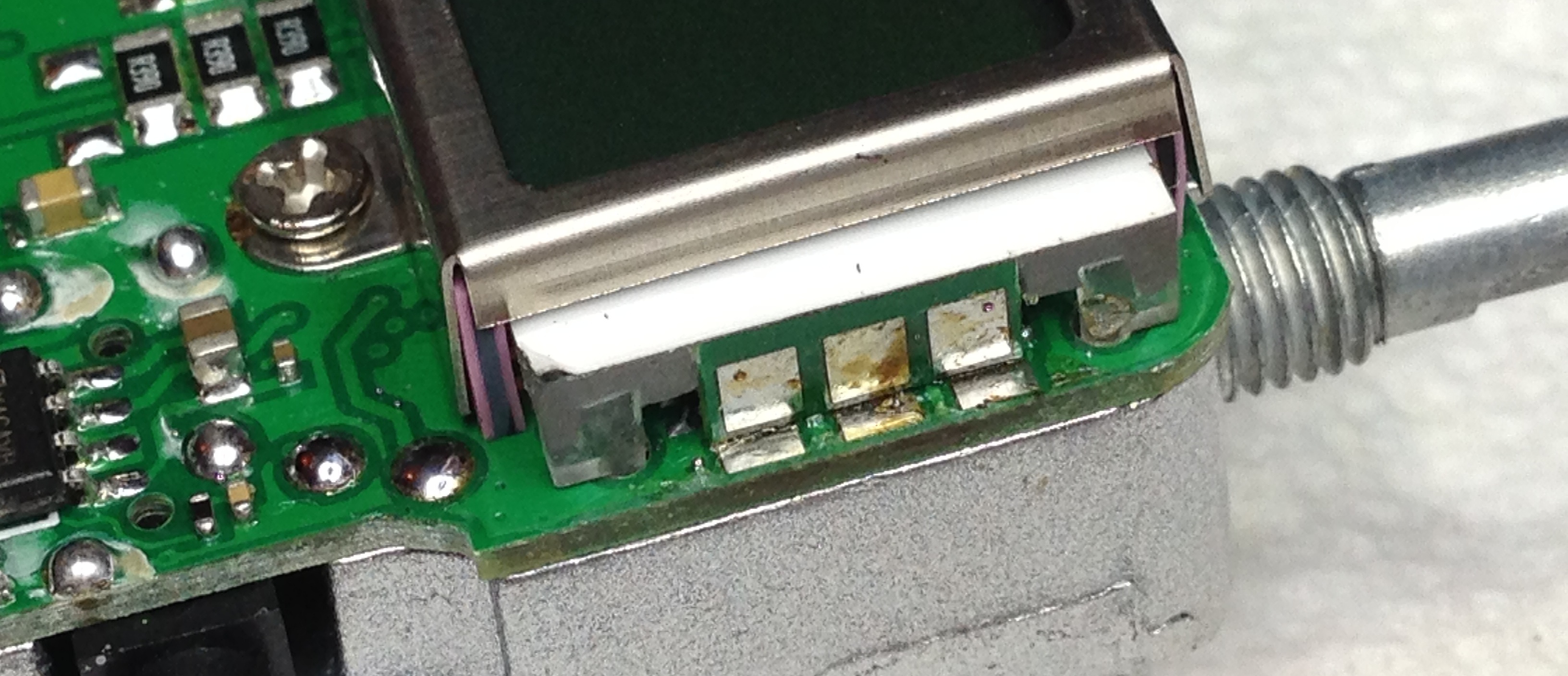
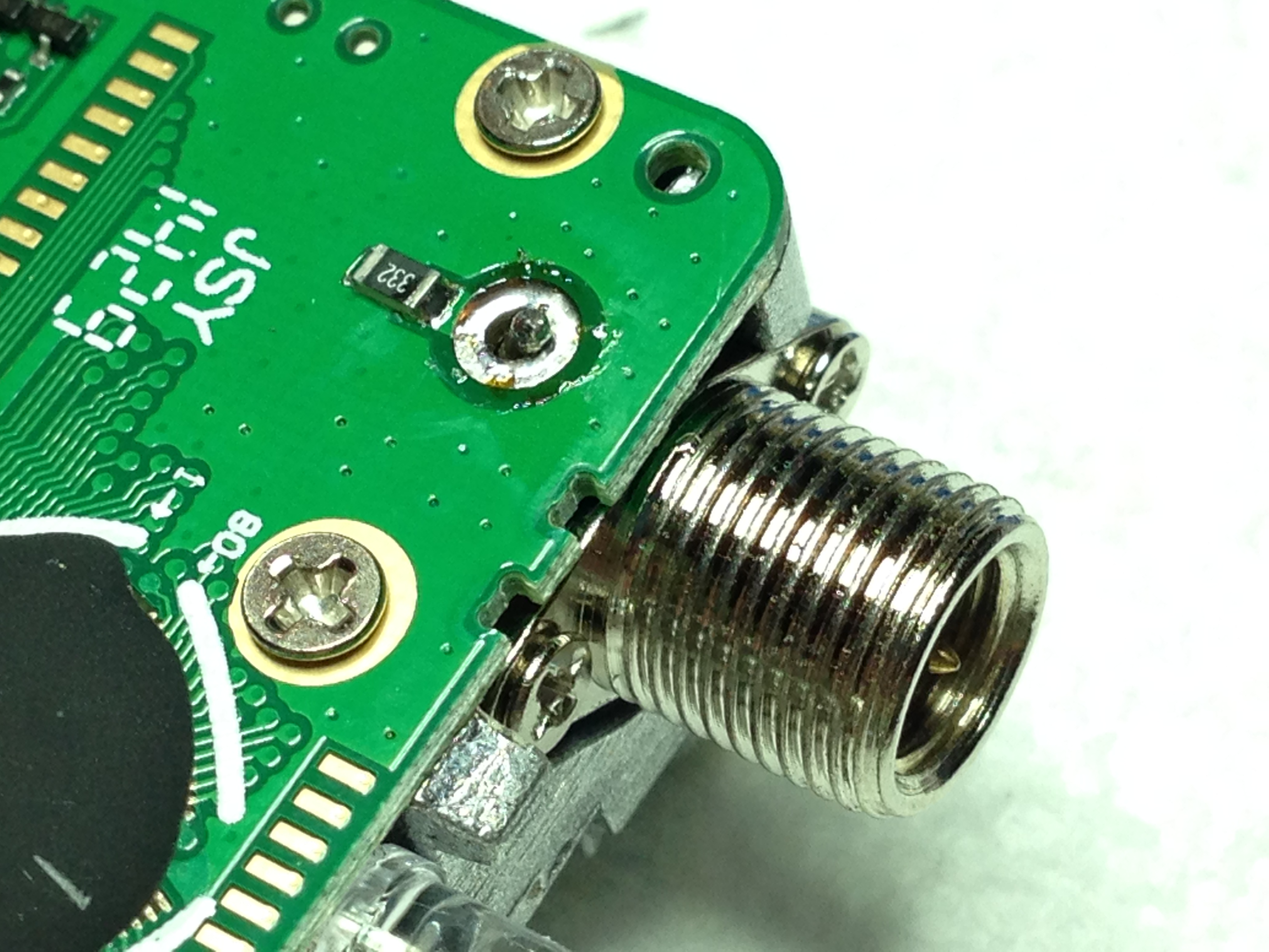
Remember: the radio comes apart without force. If you feel something is not giving, look for solder joints or screws you missed. For easy removal of the display, I used solder wick to remove the solder on the backlight connections:
 Just to be sure I desoldered the antenna connection but you can also unscrew the antenna connector and carefully force it over the aluminum ridge.
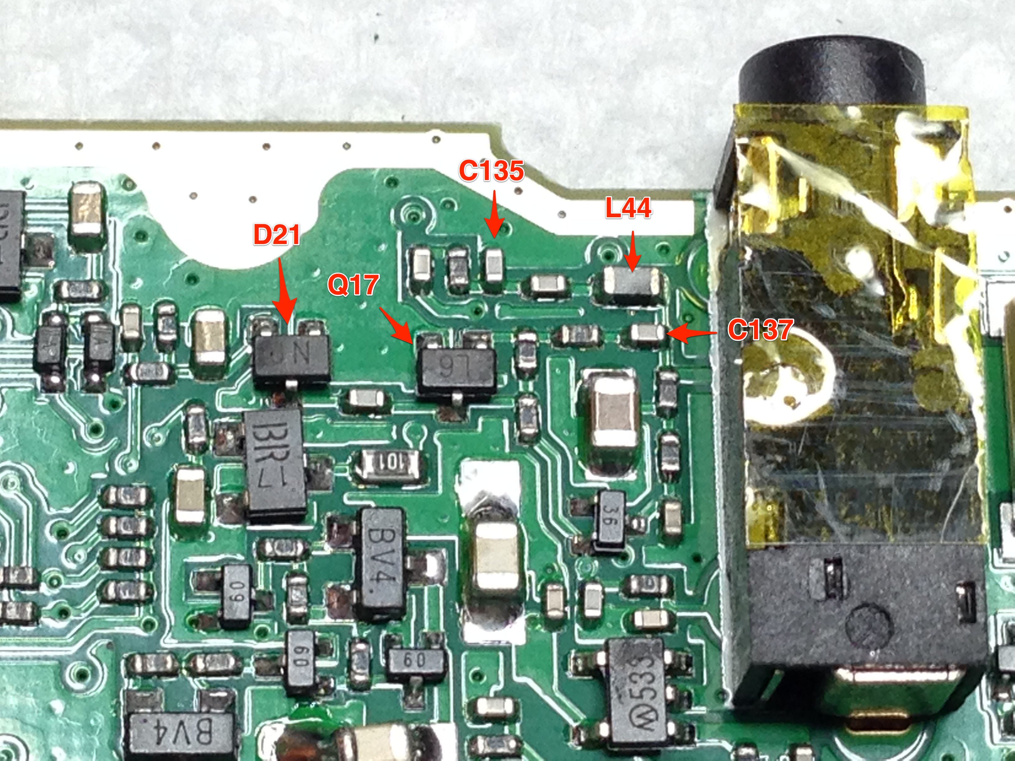
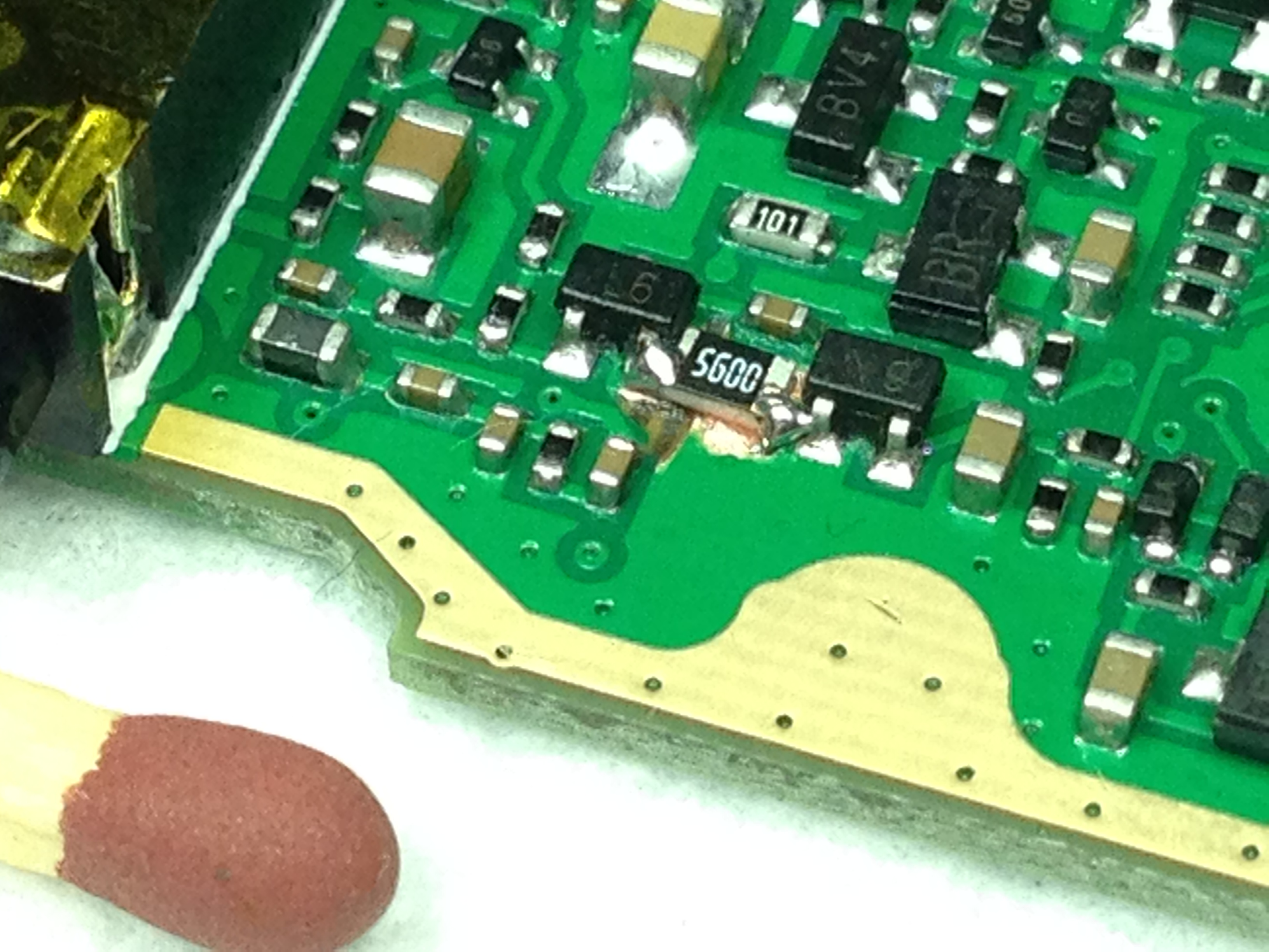
Step 2: Locate components
Locate the components in the schematic on the printed circuit board. Use a multimeter to ensure yourself that you are looking at the right components:
Step 3: Disconnect Emitter of Q17
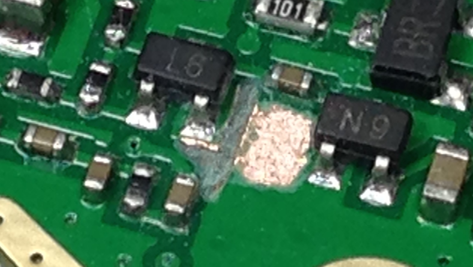
Take a (very very) small drillbit and carefully disconnect the emitter of Q17:
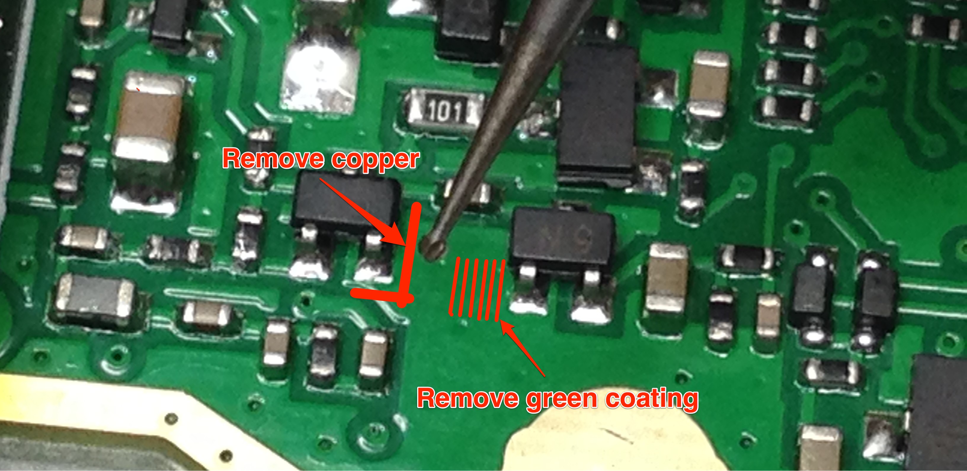
The end result should look like this:
Step 4: Add 560 Ohm resistor
Use a very small soldering iron tip and small tweezers or toothpick put the 560 (or 680) Ohm resistor in place:
In my case, the 560 Ohm resistor gave a bit too much amplification. For a bit more modest result, choose 680 (like Remco did), or anything up to 1k Ohm.
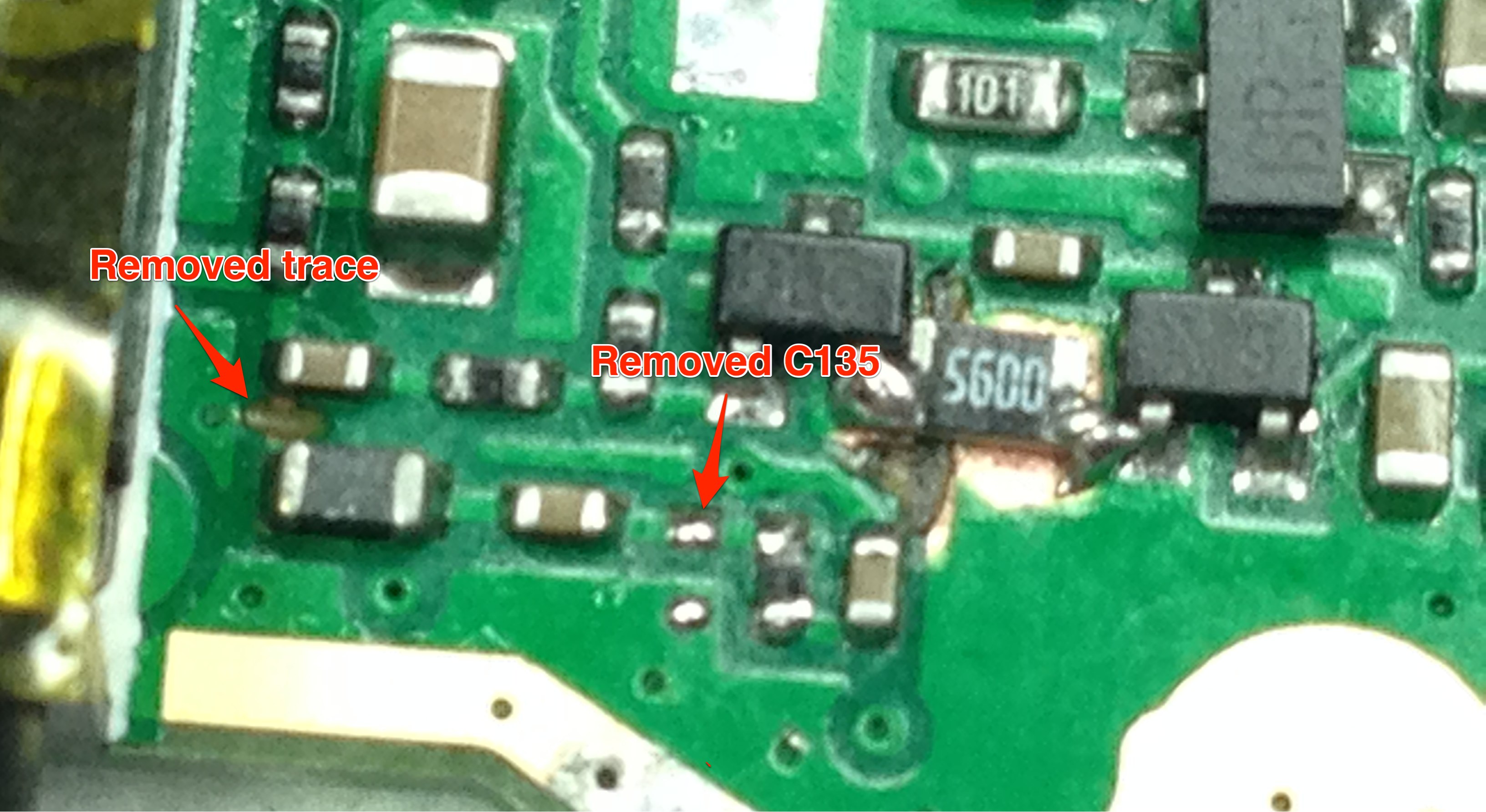
Step 5: Remove C135 and disconnect L44
Using the small tip of your soldering iron, heat up and wipe down on C135 to remove it. Take care to not hit other components, repairs will be almost impossible. Use the small drillbit to disconnect L44 by cutting the little trace between C137 and L44:
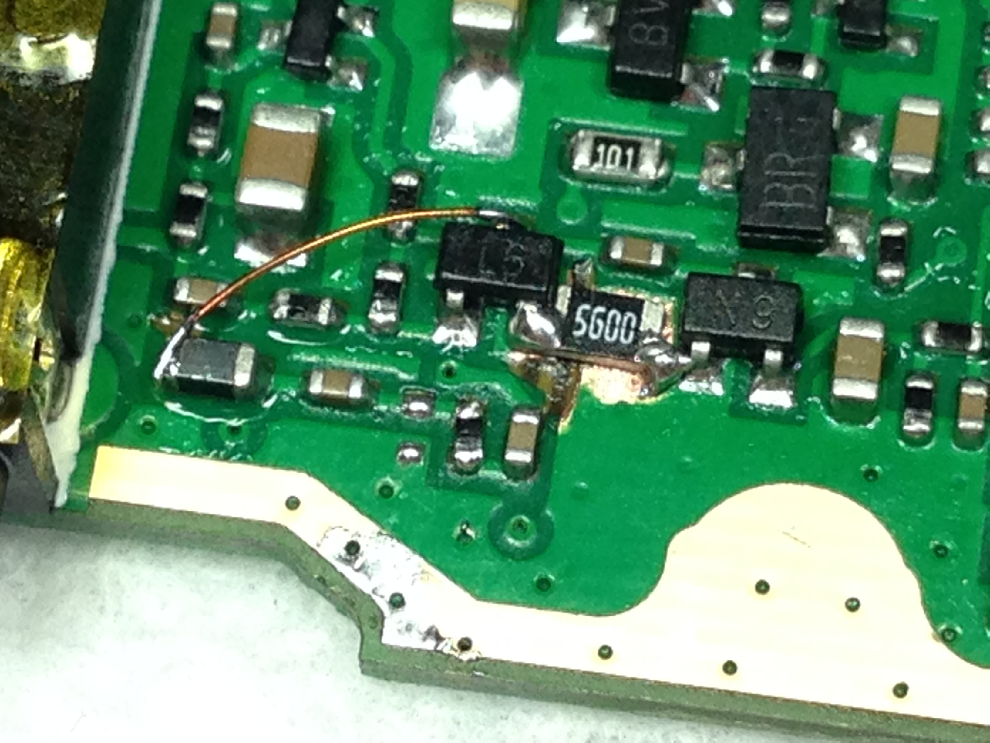
Step 6: Connect Q17 to L44
Take a small piece of enamel coated wire, strip 2mm at the ends and connect the collector of Q17 to L44:
Step 7: Close it up
Put your radio back together. Don’t forget to solder the antenna connector and backlight connections I mentioned in step 1.
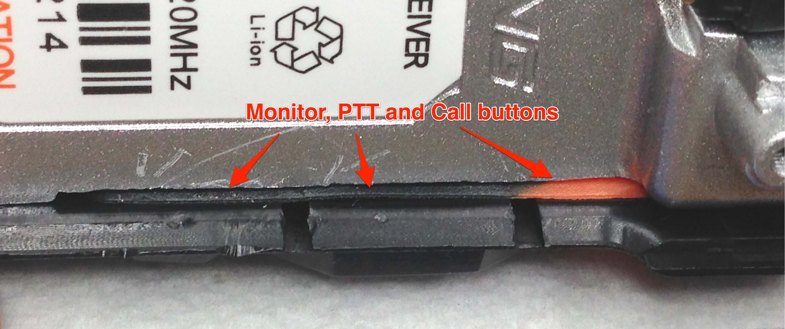
When snapping the PCB back into the case, make sure that the rubber of the PTT button does not fold behind the PCB board. Make sure the rubber is nice and flat after inserting the PCB, like this:
Have fun with your new and improved modulation!
73, Rolf.
can i remove the push talk and convert into like talephone talking? is it posible?
Yes, by not doing this modification and reading the manual 😉 Search for “VOX”. It will be hands-free, but it will not be like a telephone.
binggo.
nice picture and good explain. plan to do this guide to my uv-5ra
thanks
Done. Used a 1k resistor and still plenty of preamplification!
Definitely a killer mod but not for the fainted heart. Had problems with the display, that “lost” a row, but I’m not going to unassembly it again to fix it! 🙂 73s from Italy
This guide is a Godsend! I have never soldered anything on a surface mount board before and was very skeptical that I could perform this mod. Due to your high resolution pictures and helpful guidance I was able to make my Baofeng HT usable!!!!! Thanks so much for taking the time and the effort to post this!!!!
is not working like it did on the older radios. The newer ones are not responding to this mod. Wonder what has changed?
I did this mod today on a spare uv-5r, I used a 680 ohm resistor, everything worked afterwards even the screen.
I used a diamond sphere bit in the dremel to carve away the copper trace at Q17, and instead of cutting the small trace by L44 i desoldered the inductor and stood it up, it made it easy to solder the small copper wire to Q17. an interesting mod that increased my Mic level.
It’s not working in my UV-5R+ either. I double checked it but my voice isn’t coming trough anymore. Any idea what might be the problem? There’s just noise. Beeps, DTMF, etc. are working perfectly fine.
73, Michael
As it turned out, I picked the wrong resistor. I was off by a factor of 10. Now it works like a charm.
Thank you, i bought an UV-5R and after unboxing i did this mod. Works PERFECTLY with a 1k resistor and the modulation is more than enough boosted.
Hi there..
I did the mod and have had some great reports re audio…but with external mic I get howling oscillation on audio.. Have you tried an external mic at all please? John.. G4EIJ Bristol.. UK
Hi John, no I don’t use an external mic on the Baofeng, and I don’t have one to check so I don’t know if mine would do that too. I think this requires a deeper dive into the schematics. I’ve found a pdf here, maybe this will help you track down the problem: http://www.radioscanner.ru/files/download/file14137/shema-baofeng-5r.pdf
Many thanks for your reply.. Nothing jumps out as obvious.. Maybe some hi f decoupling Of the mic required..
Your detailed description was extremely helpful, so thank you very much. I’ve done fine soldering before, but nothing came close to this challenge! I found myself squinting with one eye through a magnifying glass, with my nose about two cms from the pcb and the hot soldering iron, soldering a component that I couldn’t even see with the naked eye!!
When I reassembled my unit the display didn’t work, but this was quickly solved by carefully aligning the flexible strips with the contacts on the pcb..So thank you again..
John. G4EIJ
Can this be done on the UV-5R in the same way as shown here for UV-5RA?